EQUIPMENT & SYSTEM COMPONENTS

PoE lighting products.
Engineered to work together.

Explore the technology behind commercial power over Ethernet lighting—from compatible LED luminaires and high-power network switches to controllers, sensors and tested cabling.

Discuss Your Project
INTERACTIVE UNIFI SWITCH SIZING

Choose your fixture type and quantity.

See the required LED drivers, 90 W PoE port allocations, available UniFi switch models, switch quantities and total power headroom.

Open the UniFi Lighting Planner
SPECIFICATION-LED EQUIPMENT GUIDE

Documented equipment. Verified installations only.

Secure Luma uses UniFi networking hardware exclusively. We require documented, model-specific UniFi-to-driver-to-fixture testing before a lighting product is installation-qualified. Other light fixtures below are research references—not approved combinations.

No third-party lighting combination is currently approved for installation.Published ratings are not proof of working end-to-end dimming, control, startup and failover. We will only recommend models after testing.
See the qualification stages and current SL-001 test candidate →
4 UniFi reference products
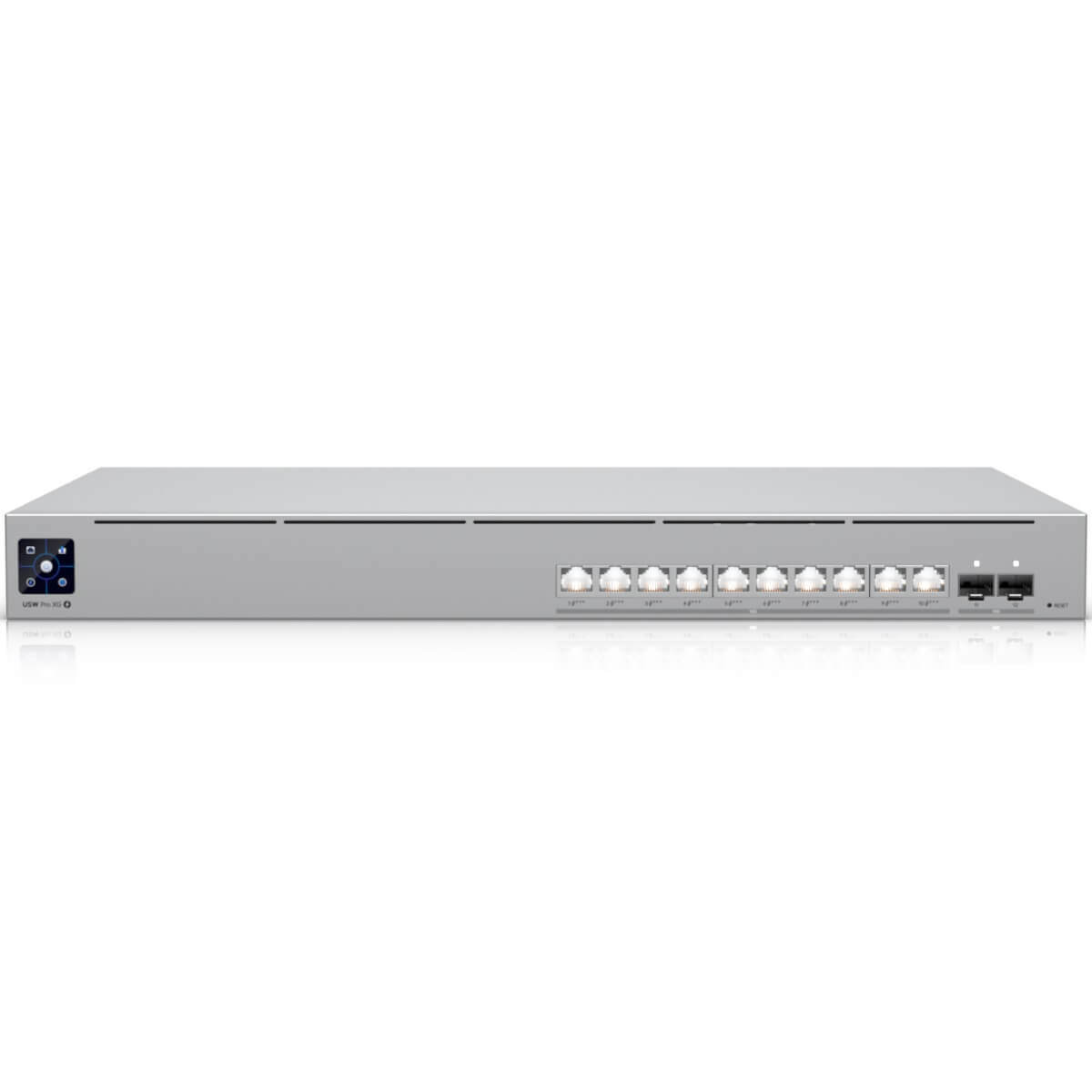
Manufacturer reference image of UniFi Pro XG 10 PoE rack-mount Ethernet switch
UNIFI NETWORK SWITCHES

UniFi Pro XG 10 PoE

USW-Pro-XG-10-PoE

POWER SPECIFICATION10 × 90 W / 400 W total
  • 10 IEEE Type 4 PoE+++ ports
  • 400 W total PoE budget
  • Up to 90 W at each eligible switch port
Which cable is needed for this item?

Main connection: Each Type 4 endpoint run: 4-pair 23 AWG solid bare-copper Cat6A with rated terminations; riser CMR, plenum CMP, outdoor OSP as applicable.

Important: Rack power: properly rated AC feed/UPS. Optional proprietary UniFi RPS DC cable to USP-RPS input (not Ethernet). Fiber or DAC uplink only if the topology requires it.

View connection diagram →
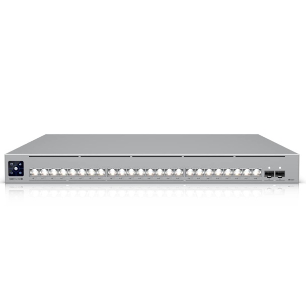
Manufacturer reference image of UniFi Pro XG 24 PoE rack-mount Ethernet switch
UNIFI NETWORK SWITCHES

UniFi Pro XG 24 PoE

USW-Pro-XG-24-PoE

POWER SPECIFICATION24 × 90 W / 720 W total
  • 24 IEEE Type 4 PoE+++ ports
  • 720 W total PoE budget
  • Up to 90 W at each eligible switch port
Which cable is needed for this item?

Main connection: For high-power PoE: individual 4-pair 23 AWG solid-copper Cat6A runs, tested at the required length; select CMR/CMP/OSP jacket for the route.

Important: AC/UPS power and any optional USP-RPS use separate power cables. An RPS connection is not an Ethernet uplink or additional PoE budget.

View connection diagram →
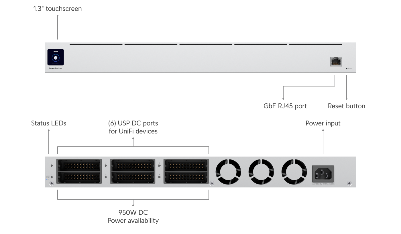
UniFi USP-RPS official rackmount redundant power system product photo
UNIFI / DC POWER REDUNDANCY

UniFi USP-RPS

External redundant DC power for eligible Pro XG switches

KEY SPECIFICATION6 ports · 600 W / 350 W shared DC rails
  • Pro XG 10 PoE and Pro XG 24 PoE have an RPS DC input
  • 52 V 600 W and 11.5 V 350 W output rail limits
  • Not a UPS; does not increase aggregate PoE capacity
Which cable is needed for this item?

Main connection: USP-RPS → supported UniFi RPS input: compatible UniFi proprietary DC/RPS cable; NOT RJ45, Cat6A, or a PoE cable.

Important: USP-RPS also needs a rated AC supply (and a separate UPS if battery runtime is desired). Validate failover load on its shared 52 V and 11.5 V rails.

View connection diagram →
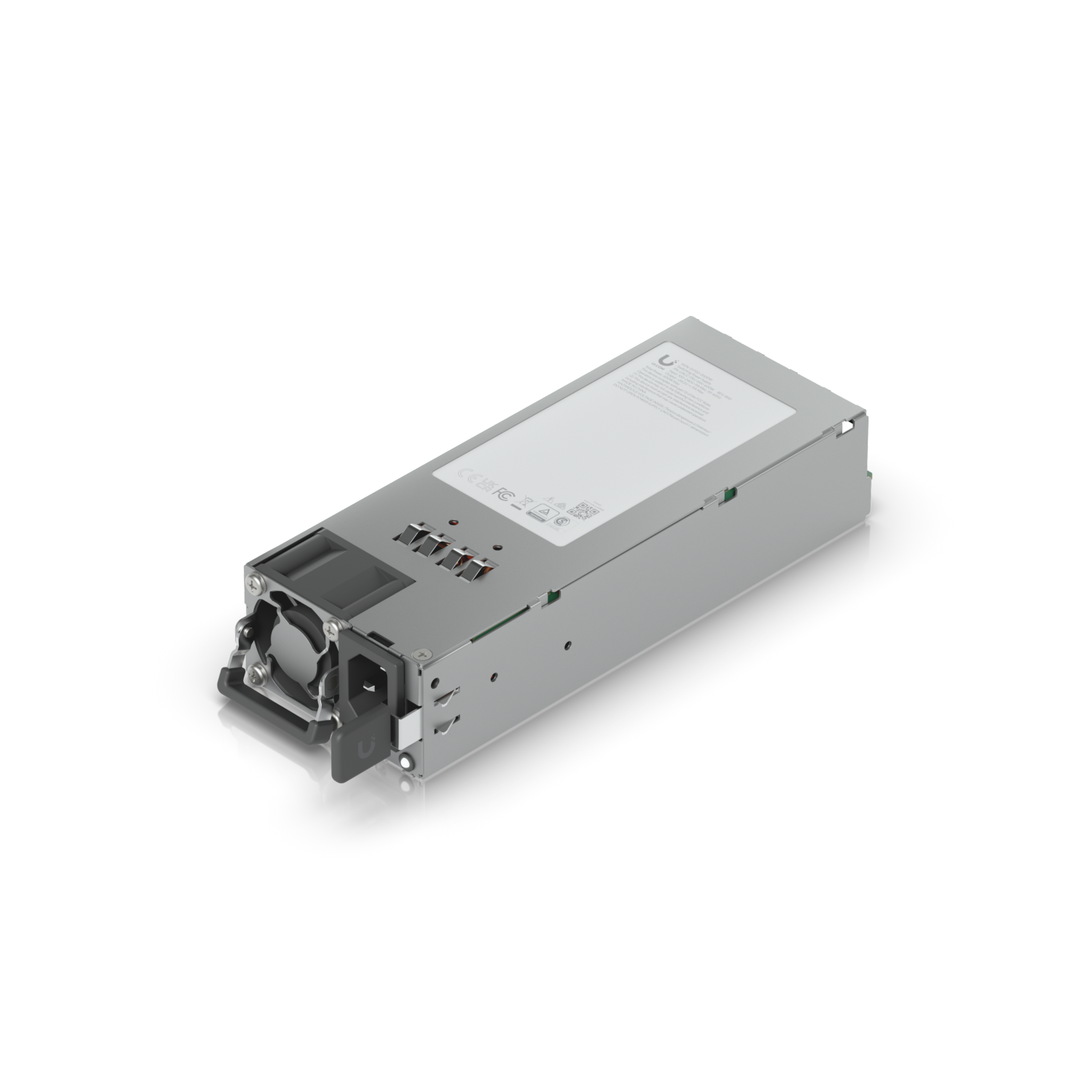
UniFi 600 W hot-swappable power module used in Enterprise Campus PoE switches
UNIFI / CAMPUS HOT-SWAPPABLE PSU

Enterprise Campus 600 W PSU

UACC-PSU-54V-600W · modular AC power supply

KEY SPECIFICATION2 × 600 W modules / Campus 24
  • 1,050 W PoE availability with shared PSU mode
  • 450 W PoE availability with redundant PSU mode
  • Integrated hot-swap architecture; external USP-RPS not used
Which cable is needed for this item?

Main connection: 600 W PSU module → Enterprise Campus chassis: slides into the matching hot-swap PSU bay. No external Ethernet or RPS cable is used for the PSU module.

Important: Each module requires an appropriately rated AC power cable/source. For output PoE devices, use solid-copper Cat6A as designed; 1,050 W shared versus 450 W redundant budget depends on PSU mode.

View connection diagram →
IMPORTANT TECHNICAL DISTINCTION

Per-port rating ≠ total switch capacity.

An eight-port switch may support 90 W PoE++ on each eligible port while having a 500 W overall budget. The actual design must consider total connected load, losses, thermal conditions and manufacturer compatibility.

Understand PoE Power Planning

Images and specifications are sourced from the manufacturers’ published materials; names and marks belong to their respective owners. Products are displayed for educational comparison, not as an authorized reseller catalog. Verify current specifications, compliance, support and photo-reuse permissions with each manufacturer before public marketing.

COMPATIBLE BY DESIGN

Six building blocks of a connected lighting system.

Secure Luma specifies system categories according to each project's photometric needs, network limits, operating conditions and manufacturer interoperability. These are equipment categories—not a promise that every product is interchangeable.

01SYSTEM COMPONENT

PoE LED Luminaires & Lighting Nodes

Commercial PoE LED fixtures and compatible lighting nodes

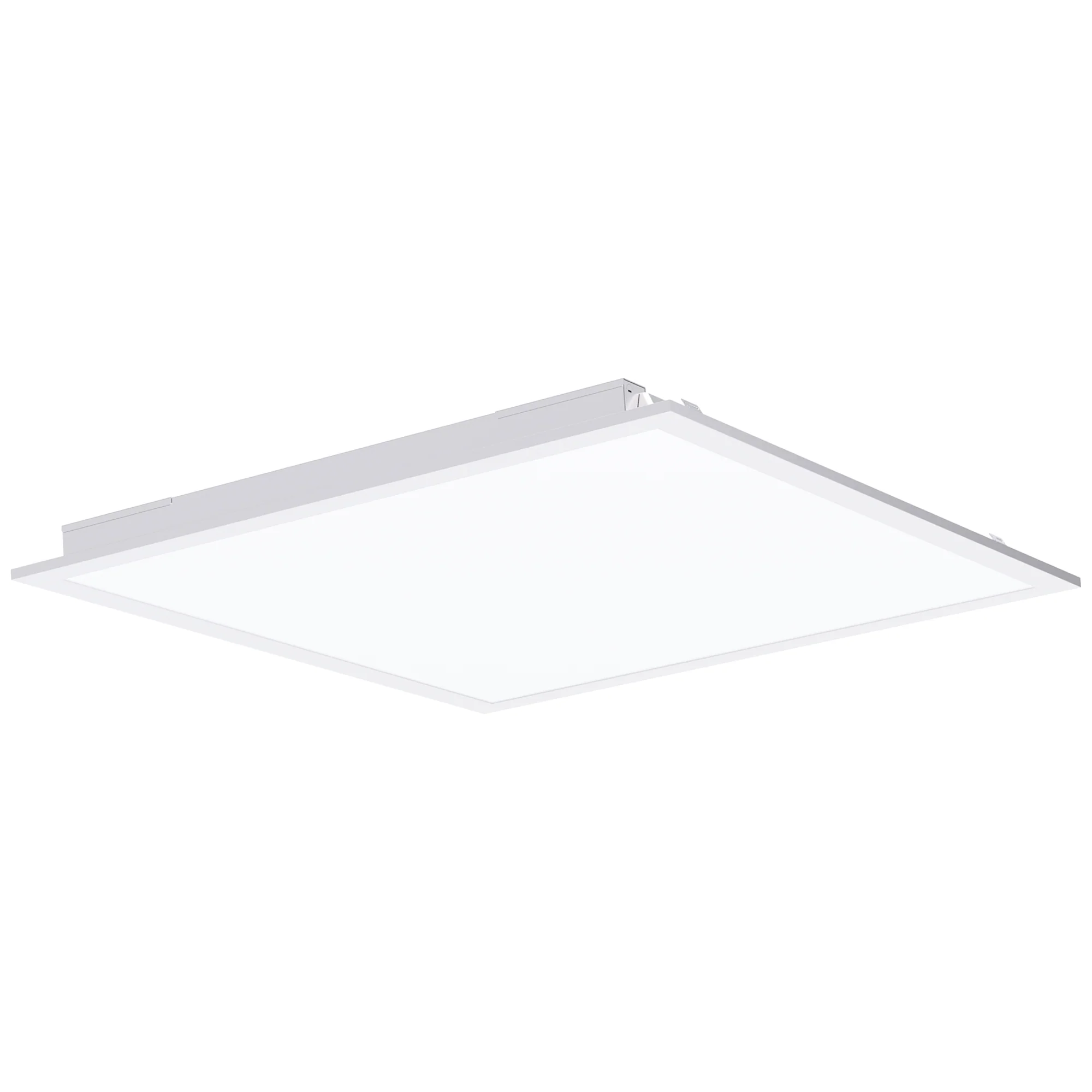
Choose troffers, linear fixtures, downlights, suspended panels and other supported formats based on light output, beam distribution, dimming and the actual PoE power available. Some luminaires connect directly to Ethernet; others need a compatible PoE lighting node or driver.

Selection checklist

  • Light output (lumens), efficacy and distribution
  • PoE class and fixture/driver input draw
  • Compatible dimming and control interface
  • Mounting, operating environment and listing
02SYSTEM COMPONENT

PoE+ / PoE++ Network Switches

Power delivery and data distribution

Lighting-capable Power over Ethernet switches provide electrical power and communications to compatible fixtures or nodes. The port rating, shared power budget, switch power supplies and heat load all matter—not just the port count.

Selection checklist

  • IEEE 802.3af / at / bt type and class
  • Per-port output and aggregate PoE budget
  • UPS capacity and network resiliency
  • Switch thermal load, location and serviceability
03SYSTEM COMPONENT

Lighting Controllers & Gateways

Central control and smart integration

Lighting applications or gateway/controller devices can manage scenes, zones, dimming, schedules, and—in supported ecosystems—remote monitoring or connections to building management systems.

Selection checklist

  • Fixture and switch ecosystem compatibility
  • On-premises versus cloud capabilities
  • Role-based access and cybersecurity
  • API, protocol and BMS integration requirements
04SYSTEM COMPONENT

Occupancy & Daylight Sensors

Automation that responds to the space

Occupancy/presence sensors and daylight sensors can adapt light levels to activity and available daylight. Supported smart wall controls let users make local changes without disrupting centralized policies.

Selection checklist

  • Coverage, location and detection approach
  • Daylight calibration and task-lighting needs
  • Sensor and controller interoperability
  • Override behavior and local control
05SYSTEM COMPONENT

Cat6 / Cat6A Cabling & Connectivity

The structured cabling backbone

Properly selected copper cabling, patch panels, terminations and labeling connect the lighting endpoints. Cable gauge, length, bundling and temperature are important when delivering higher PoE power.

Selection checklist

  • Cable category, conductor size and type
  • Channel length and pathway design
  • PoE heating, bundle derating and losses
  • Documented testing and labeling
06SYSTEM COMPONENT

Power Protection, Racks & Monitoring

Design for maintenance and uptime

Rack infrastructure, appropriately rated UPS, network segmentation and ongoing monitoring help deliver a serviceable lighting installation. Emergency illumination must be designed separately to meet all applicable requirements.

Selection checklist

  • UPS runtime and load calculations
  • Optional USP-RPS on supported Pro XG models, or dual hot-swappable Campus power modules
  • Switch, gateway and controller backup
  • Monitoring, access and replacement plans
  • Code-required emergency egress provisions
NETWORK-POWERED LIGHTING / ENGINEERING REFERENCE

Can UniFi switches power PoE lighting?

Yes—select UniFi switches can supply IEEE-standard PoE power to compatible LED lighting nodes or drivers. A successful system still depends on the actual fixture's required PoE type, delivered wattage, the switch's total power budget, cable design and lighting-control platform.

THE IMPORTANT DISTINCTIONPower delivery ≠ lighting control

UniFi Network manages switch ports and PoE. Dimming, scenes, occupancy logic and lighting zones typically require the compatible lighting manufacturer's controller or software—not UniFi Etherlighting port LEDs.

01 / PRO MAX

UniFi Pro Max 24 PoE

USW-Pro-Max-24-PoE

16PoE++ ports
400 WTotal PoE budget
60 WMax per PoE++ port

A practical reference for a compact lighting distribution zone. Eight additional ports support PoE+.

Official UniFi specifications ↗
02 / PRO MAX

UniFi Pro Max 48 PoE

USW-Pro-Max-48-PoE

16PoE++ ports
720 WTotal PoE budget
64 WMax per PoE++ port

Higher aggregate power and more network ports, but only 16 PoE++-capable ports.

Official UniFi specifications ↗
03 / PRO XG

UniFi Pro XG 24 PoE

USW-Pro-XG-24-PoE

24PoE+++ ports
720 WTotal PoE budget
90 WMax per port

Higher-powered per-port options for appropriately matched IEEE 802.3bt Type 4 devices.

Official UniFi specifications ↗
04 / CAMPUS

UniFi Enterprise Campus 24 PoE

ECS-24-PoE

24PoE+++ ports
1,050 WShared PSU mode*
90 WMax per port

Two hot-swappable 600 W AC PSU modules. Shared mode supplies 1,050 W total PoE; redundant mode supplies 450 W. Enterprise Campus does not use an external USP-RPS.

Official UniFi specifications ↗
ILLUSTRATIVE CAPACITY / NOT A FIXTURE APPROVAL

How many lighting devices could one switch supply?

The examples below use a 30 W or 50 W power allocation per connected device at the switch (PSE), only the higher-power ports listed above, and reserve 20% of the total switch PoE budget for planning headroom. This is not a confirmed count for any particular LED product.

UniFi switch30 W / device50 W / deviceMain limiting factors
Pro Max 24 PoEUp to 10Up to 6400 W budget; 16 high-power ports
Pro Max 48 PoEUp to 16Up to 1116 high-power ports; 720 W budget
Pro XG 24 PoEUp to 19Up to 11720 W aggregate budget
Enterprise Campus 24 PoEUp to 24Up to 16Assumes 1,050 W shared PSU mode*

Illustrative arithmetic: min(eligible high-power ports, floor(0.8 × switch PoE budget ÷ per-device PSE allocation)). Real installed count depends on actual measured power draw, negotiation, cable loss and length, other connected devices, input voltage, PSU operating mode, future expansion margin and applicable code. A 50 W fixture rating is not automatically equivalent to a 50 W PSE allocation. A separate lighting-controller integration test is required.

WHAT LIGHTS CAN BE USED?

Choose the fixture or driver first—then the switch.

Direct PoE LED panels, recessed fixtures, low-voltage drivers and sensors from lighting manufacturers may be candidates, but Secure Luma must verify each exact device's IEEE 802.3af/at/bt class, required input power, connector/cabling requirements and controller ecosystem with its maker before pairing it with UniFi.

Read the technical FAQ
SPECIFICATION FIRST / CABLING

Which cable goes with each component?

This is an engineering selection guide—not a blanket installation approval. A lighting manufacturer's test record, approved driver diagram, cabling pathway and applicable local code determine the final bill of materials.

Our preferred new high-power PoE network runCat6A, 4-pair, 23 AWG solid bare copper, rated Cat6A RJ45 termination
Choose the correct jacketCMR for applicable risers · CMP for plenum air spaces · outdoor-rated OSP/UV/wet where exposed
AvoidCopper-clad aluminum (CCA), slim high-power patch cords, or unlabeled cable with no temperature/PoE information
Equipment / pathCable or connection typeImportant limit or verification
UniFi switch → Type 4 PoE driverSolid-copper Cat6A, 23 AWG, 4 pair, RJ45 (design preference)Check 90 W PSE port, 71.3 W PD planning power, 100 m channel ceiling only where the device/channel allows; bundle heat and loss matter
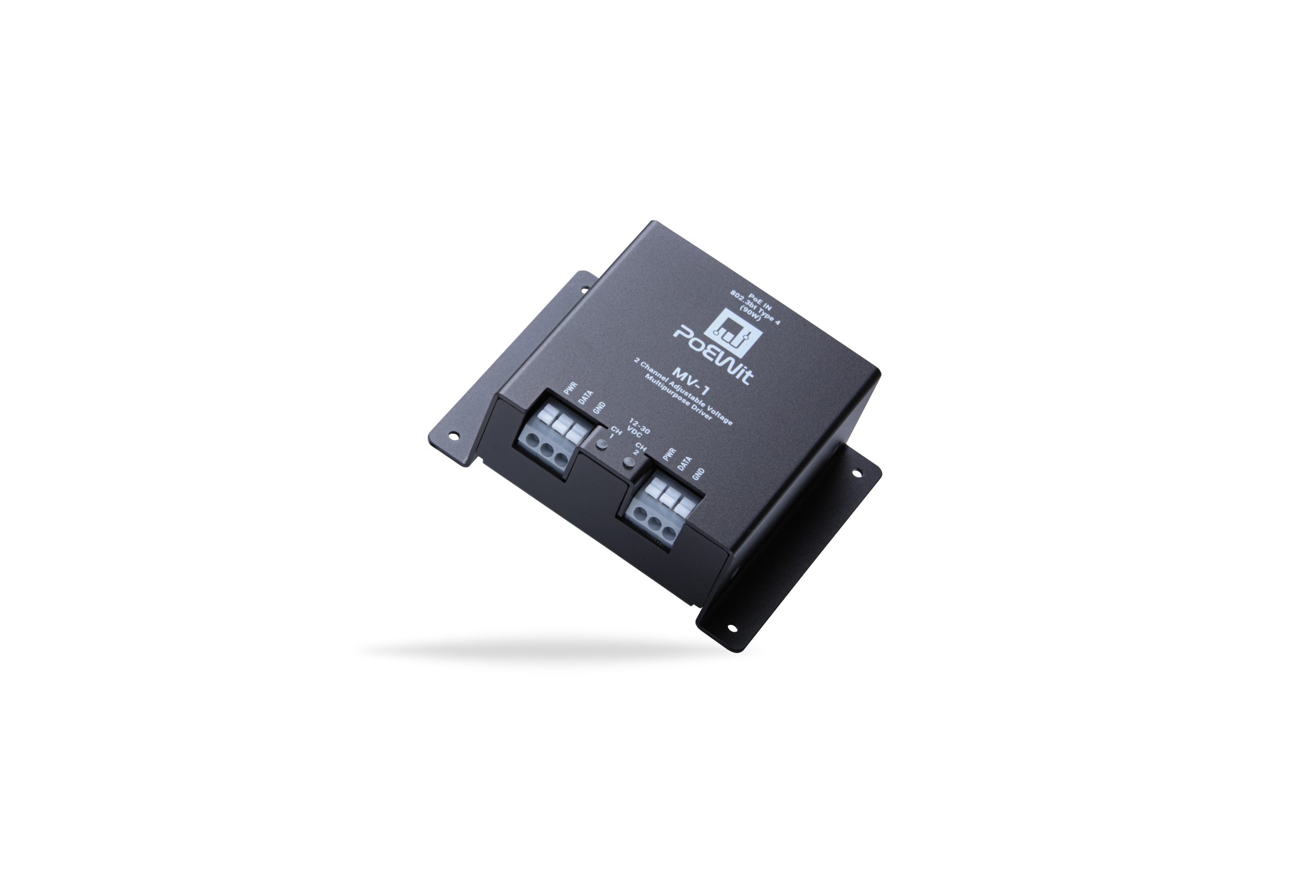
PoEWit UPD-1 → matching lightFull-size Cat6 or higher patch cable, correct vendor splitter and factory-tuned outputPoEWit UPD manual: 25 ft maximum driver-to-light; do not use slim / ultra-slim Cat6
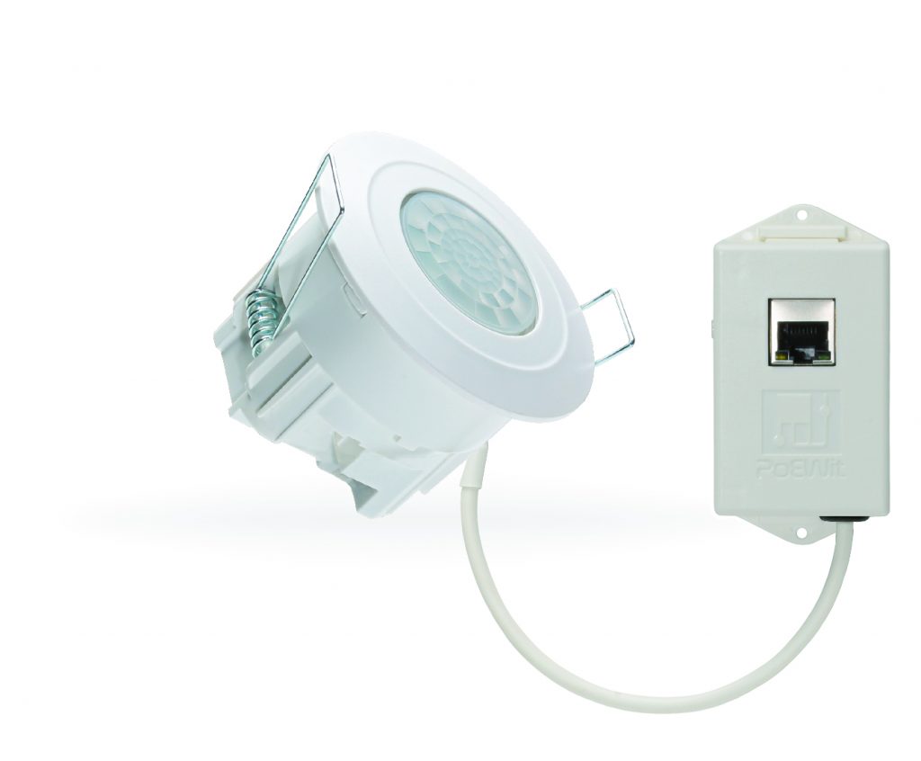
PoE sensor → switchSolid-copper Cat6 RJ45, jacket selected for locationCheck sensor's actual PoE class and integration with the lighting controls; Type 4 not inherently required
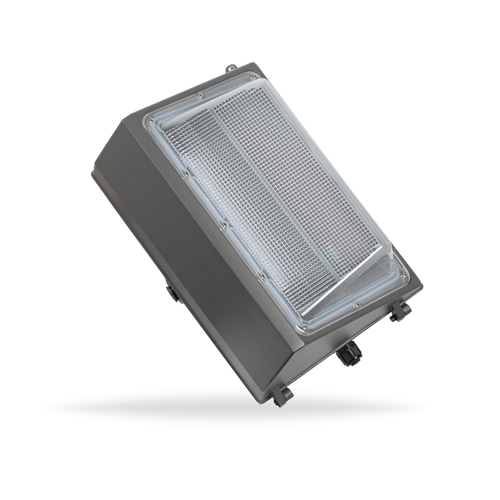
Exterior wall packOutdoor/UV/wet-rated solid-copper Cat6A in approved pathway and weather-rated enclosureConfirm manufacturer's pass-through and upstream input before any UniFi recommendation
USP-RPS → Pro XG switchCompatible proprietary UniFi DC/RPS power cableNOT a Cat6 cable; separate RPS AC feed, shared output-rail check, and UPS strategy
Campus hot-swappable PSUInternal modular power-supply bay + rated AC power feed(s)No RPS cable; design for shared versus redundant PoE mode; separate Ethernet data/PoE cabling

Electrical safety and code: use listed cable/connectors for the installation environment; determine pathways, fire ratings, 4-pair PoE heat and local permitting with qualified installers. Do not assume any manufacturer example is an approved UniFi lighting system.

SYSTEM PLATFORM RESEARCH

Compare the ecosystem, not just the fixture.

PoE lighting may depend on proprietary driver and control platforms. Before any specification is approved, we examine fixture-driver pairings, control behavior, future serviceability and the total installed power budget.

POWER BUDGET MATTERS

PoE, PoE+ and PoE++ power classes.

Actual fixture capacity must be checked at the powered device (PD), not just at the switch port (PSE). Standardized power levels below are maximum reference values, not guaranteed usable luminaire wattage in every design.

Important for high-bay spaces

Many high-output industrial LED fixtures exceed the power available from a single conventional PoE port. They may require purpose-designed power architecture, a compatible node arrangement or conventional lighting power.

IEEE 802.3 PoE reference power at source and device
Type / standardPower at switch (PSE)Power at device (PD)Design consideration
Type 1 · 802.3af15.4 W13 WLower-power controls and endpoints
Type 2 · 802.3at30 W25.5 WModerate-power compatible devices
Type 3 · 802.3bt60 W51 WHigher-power devices with four-pair PoE
Type 4 · 802.3bt90 W71.3 WHighest standard PoE class shown; verify fixture draw and losses

Reference: Ethernet Alliance — IEEE 802.3 PoE types and power levels. Additional design reference: U.S. Department of Energy — PoE cable energy losses.

SYSTEM ARCHITECTURE

From the network closet to the lighting zone.

A typical design combines a lighting-capable PoE switch, certified cabling, compatible fixtures or nodes, and a controller or software layer. Sensor data and commands support automated operation when the equipment ecosystem allows it.

  • Network and power budget sized before product selection
  • Compatible drivers, lighting nodes and sensors
  • Clear commissioning and maintenance documentation
  • Separate review of life-safety and emergency lighting
See the Full Architecture
EQUIPMENT SPECIFICATION SUPPORT

What to review before ordering PoE lighting products.

Product selection is more than matching RJ45 connectors. Confirm the entire system's performance, maintainability and code requirements.

Power & performance

Port and aggregate power budgets, lumens, lux targets, color temperature, CRI, cable losses and fixture electrical ratings.

Controls & integration

Approved switch-device compatibility, controller capabilities, sensor coverage, remote access policies and protocol support.

Safety & service

Product listings, cabling methods, required emergency circuits, support lifecycle, warranty terms and service procedures.

SPECIFY THE RIGHT SYSTEM

Plan your lighting around the building, not a guess.

Share your fixture count, layout, operating hours and control requirements. We can discuss the power budget and product compatibility for your project.

Request a Consultation